For a while, I was interested in the attempts of a former colleague to start up a business in wing sails for commercial shipping. We drifted apart, but it gave me pause for some independent thinking about sails and sailing.
It has often been observed that because the water surface acts like a mirror plane for both the underwater ship and the part above the water, a sailboat is really two "half airplanes" joined at the hip.
The underwater ship can be seen as one half of a manta ray-like "submarine glider" on its side, in infinitely deep water, with the keel as one of the wings and its mirror image as the other wing. Actually, an airplane engineer would call the symmetrical two keels from tip to tip "the wing".
Similarly, the part above the water can be mirrored to give a symmetrical airplane ( on its side ) in free air. Anthony Fokker or his chief designer Reinhold Platz are alleged to have flown a "glider" like this over the sand dunes along the Dutch coastline, but the story may be apocryphal, and the photograph and sketch below may be fake. A prank like this would not have been beyond someone like Fokker. Still, the idea is sound.
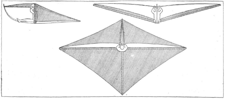
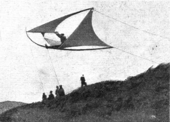
Figure 1 : Platz glider, mirrored sloop rig
A wing deflects air down, which makes it generate lift upward. The wing also generates a much smaller drag force backwards. The aerodynamic resultant of lift and drag is therefore tilted slightly backwards relative to the flight path.
The nose down flight path of a glider tilts the aerodynamic resultant forward again back to the vertical, where it makes equilibrium with gravity. The net force on the glider thus becomes zero and the glider can go on indefinitely in a steady descending flight until the height runs out. Another way of looking at this is that a small component of the gravity force pulls the glider forward along its flight path, cancelling the drag component of the aerodynamic force.
There is a wonderful body of aerodynamic theory due to Prandtl, which describes the quite complex forces involved in incredibly simple equations. This theory is partly described elsewhere on this website in the section on propeller theory, but it can also be looked up in any textbook on aircraft engineering.
We will summarize here the bare minimum needed for a simple, but very instructive view on sails and sailing.
The lift on a wing is traditionally expressed in a non-dimensional "lift coefficient" CL. We just give the definition :
| (1) |
Here L is the lift, ρ is the density of the medium, in this case air; V is the relative wind velocity, and S is the wing planform area.
The lift goes up linearly with angle of attack, starting from zero for a wind vane aligned with the flow, until a certain angle is reached where the air can no longer follow. This angle of attack is called the "stalling angle". For very good plain wings the stalling angle is around 16°, and the maximum lift coeffient is around CL = 1.6. For a ship's sail, the maximum lift coefficient is never going to be more than CL = 1.0.
For reasons too deep to go into here ( but see the section on propellers ), a wing of infinite span ( or wall to wall in a wind tunnel ) leaves no net deflection behind. It sucks up air ahead of it, and dumps it downwards again behind it, leaving no net deflection when looked at from a distance. It just makes a local bump in the flow near the wing.
Wings of finite span on the other hand do have net downflow. The air curls inwards around the tips, and this causes a downward flow in the middle of the wing which persists "forever", i.e. long after the airplane is out of sight. This is called the wing wake, or downwash.
By an interesting derivation ( again, see the section on propellers), the downwash velocity w, usually expressed in the downwash angle αw ≡ w / V, that persists far behind the wing is :
| (2) |
The factor of 2 is usually not seen in aircraft texts, because aircraft texts are interested in the part of the downwash at the wing itself, and for reasons of principle, again too deep to go into here, this is exactly half the value in the far wake. The non-dimensional factor A is the so-called "aspect ratio" of the wing, defined as the ratio between its span b and its mean chord c. The definition is :
| (3) |
Here b is the span of the wing, and S ≡ b . c. There is a lot of folklore around this equation, but we use a different tack. Combining (1) to (3), we find :
| (4) |
We can also write this as :
| (5) |
Now consider the deflection angle in the light of Newton's law, F = m . a. Here m . a, alias m . ( dv / dt) , can also be interpreted as the change in the momentum ( m . v ), i.e. as d/dt ( m . v ), and even as ( dm / dt ) . v. In the latter interpretation, a new quantity of mass is accelerated every second to a fixed new velocity v.
Newton's symbol for the mass flow dm / dt was m●. From (5), apparently the wing deflects a mass flow of :
| (6) |
This is a well known result from wing theory. Every second, the wing deflects a tube of air of length V, frontal area ¼ π b2, and density ρ. This is a circular tube of air that the wing flies through, with the span of the wing as the centerline of the circle. The figure show the idea. Note that this is just a schematic view : the edge of the circle is not that sharp. But the effective frontal area is correct.
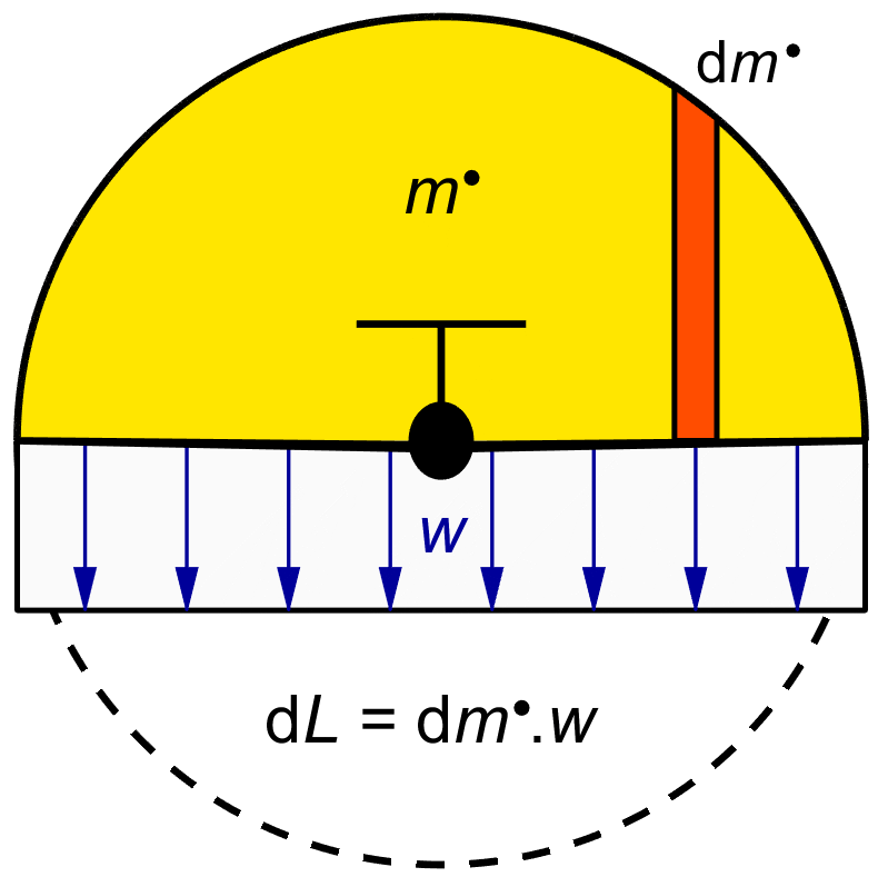
Figure 2 : Wing effective frontal area.
The effective deflecting frontal area of a symmetrical wing ( or sail ) is ¼ π b2, where b is the effective span. But of course, only the physical part of the sail above deck actually produces lift or thrust. If a ship has a mast height h and its sail area is effectively reflected in the water surface, then the sail's deflected frontal area is the top half of a circle with radius h, changing (6) into :
| (7) |
Here V is the undisturbed velocity of the relative incoming wind over the deck. The left hand side of Figure 3 shows this situation.
If there is no effective reflection in the deck or in the water surface, then the sail will act as a single wing of span h, with radius ½ h. The effective deflected frontal area will be π (½ h) 2 = ¼ π h 2, which is only half that of a properly reflected wing. The right hand side of Figure 3 show this case.
It is therefore vital to close the gap between the sail and the deck, to avoid losing nearly half of the sail's effectiveness.
If the wing "shadows" overlap, then the deflection angles of the sails simply add. If the masts are very close together, the deflection at both sails is identical, but twice the value of a single sail. If they are further apart, the rear sail will live in air deflected by the front sail, and it will have to be rigged to a slightly larger angle of attack accordingly to give its full lift. This is all easily calculated.
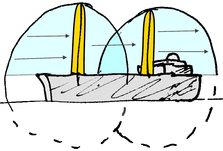
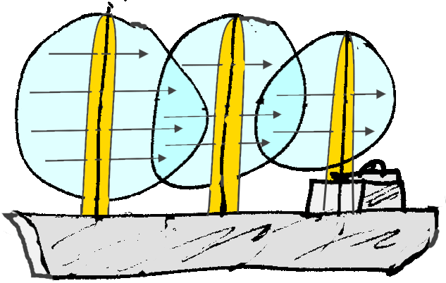
Figure 3 : Sail effective frontal area.
At a given wind speed and forward ship speed,
there is an incoming wind over the deck.
This relative wind
The relative wind is the only mass flow available for the ship to deflect. We know that the air comes in at a certain angle, and that we can change the direction of only the mass coming in through the sail frontal area. This area we cannot change, except by increasing the mast height.
The only thing we can change by rigging the sail is the deflection angle. The rule is surprisingly simple. First of all, to a first approximation ( if we disregard the small drag force ), the outgoing velocity Vout and the incoming velocity Vin are equal. The lift force is at right angles to the mean velocity, and it only changes the direction of the wind velocity vector, not its length. By Newton's law, the force is in the opposite direction of the velocity ( or momentum ) change. Let us decompose the incoming ( relative ) velocity Vin into two orthogonal components, one sideways and one along the centerline of the ship.
The change of the velocity in the sideways direction will only cause a force in the sideways direction. It will not contribute any thrust or drag in the direction of the ship's velocity through the water. The change of the wind velocity in the lengthwise direction on the other hand will only give a force in the lengthwise direction, either a drag or a thrust.
All we have to do to get maximum thrust, is to maximize the outgoing velocity ( and momentum ) in the downstream direction of the ship. Clearly, the downstream component of the outgoing wind velocity is largest when Vout points straight to the rear. Figure 4 gives the idea.
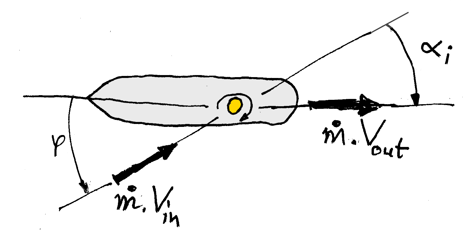
Figure 4 : The optimum deflection is straight to the rear.
Suppose the incoming relative wind V makes an angle of φ with the ship's centerline. The outgoing momentum flow m● V is ideally completely axial. The incoming component is m●.V . cos φ. The ideal thrust will be :
| (8) |
There is a limit to the angles φ which we can turn straight to the rear. A wind from behind will not be turned back to blow in the opposite direction. The most we can hope for is to stop it, like in a spinnaker sail. Even with the most elaborate wing and flap arrangements, it is unlikely that we can turn the wind by more than 90°. The factor of ( 1 - cos φ ) will not be realized in practice. It may look more like the figure below.
We see that the sweet spot for the relative wind is sideways. Winds from the front, and to a lesser degree winds from behind, soon render a sail almost completely useless. Most of the time, the relative wind is from the front quarter anyway, due to the forward speed of the ship itself. Steady winds from the side or maybe quarter behind across popular ocean trajectories are called "trade winds" for a reason.
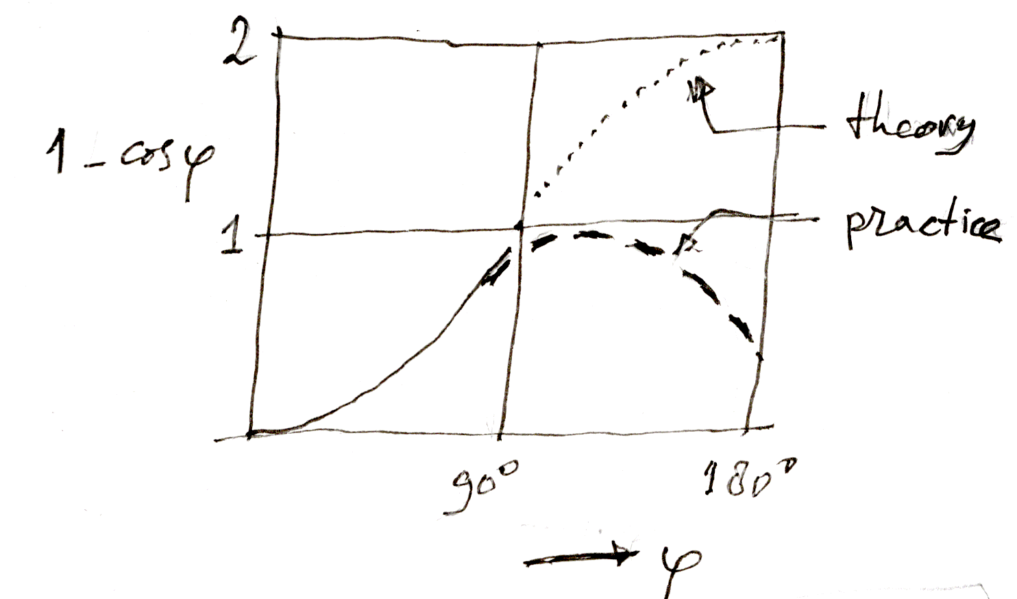
Figure 5 : Sail thrust factor with relative wind angle.
Combining the thrust (8) with the mass flow (7), we have :
| (9) |
Interestingly, the maximum thrust is limited only by mast height, not by sail area. Sail can be added, and we will see below by how much, but adding more sail than is needed to turn the wind straight to the rear will reverse the sideways component of the wind. This will only decrease the thrust and increase the drag.
Mast height, in fact mast height squared, sets the limit to the thrust a sail can deliver.
The lift required from the sail is larger than the thrust. Especially at small relative wind angles φ, most of the lift is sideways, and even massive lift gives only very little thrust.
Unfortunately, the drag losses go with the lift, not with the thrust. This is another reason why sails soon become useless in even a partial headwind. By the vector diagram for the ideal case without drag, the relation between lift and thrust is :
| (10) |
By some trigonometry, the lift required will be :
| (11) |
From (11) and (9) we see that the lift increases linearly
from zero at φ = 0,
and the thrust only quadratically
With (7) in (11) the lift required is :
| (12) |
We define an average chord ( horizontal width ) c of the sail similar to the one used in (3), by S ≡ h . c. The aerodynamic lift (1) then becomes :
| (13) |
Equating this to (12) we have :
| (14) |
The necessary sail area will depend on the angle of the incoming wind, and on the optimum ( or achievable ) lift coefficient. The maximum situation is a pure crosswind, with φ = 90°. For this case, sin ½ φ = ½√2 ≅ 0.7. The maximum lift coefficient of a sail is CL = 1.0. Substituting these values into (14) gives :
| (15) |
The sail is more than four times wider than it is high. This sheds some light on the amount of overlapping sail area that clipper ships like Cutty Sark carried, see Figure 6 below. In a pure crosswind, it seems you can never have enough sail to realize the thrust allowed by the mast height.
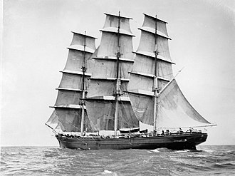
Figure 6 : Cutty Sark sail area.
- extensive Matlab VPP ( available ).
- rotor wings.
- Cousteau ( Malavard ).
- Thwaites flap.
- Autogyro sail