VORTEX THEORY
Prandtl's
approximation gives us a physical intuition
on the tip loss. His tip factor
F ( x )
represents a reduction of the effective mass flow
receiving the "full" induction on a given radius.
However,
Prandtl's
For a long time, the exact solution was difficult to compute, and only available in the form of coarsely spaced tables. This severely limited the use of the vortex method in design studies. However, with today's computing power, tables are no longer needed. The whole vortex calculation can be run in a fraction of a second on a laptop computer.
A Matlab © section elsewhere on this website gives a number of simple downloadable Matlab© scripts, which can be easily ported to other languages, like Python or Octave, which support a toolbox for matrix inversion.
This chapter introduces the basic idea of classical vortex theory, with the aircraft wing as a baseline. The next chapter applies it to the propeller.
The basic building block of vortex theory is the line vortex. A line vortex is like a little tornado. A vortex of "circulation" strength Γ ( Greek capital letter Gamma ) creates a circular velocity v around its centerline, the strength of which is by definition inversely proportional to the distance r from its center. The circulation is defined as the integral of the velocity along a circular path around the center. The equation therefore contains a factor of 2 π :
| (21.1) |
This can also be written as :
| (21.2) |
Figure 21.1 gives the graph of velocity versus radius, looking down the axis of the vortex line. The ideal vortex has infinite velocity at the core. There is no calm "eye of the storm". This makes the concept very clean, but it complicates the math.
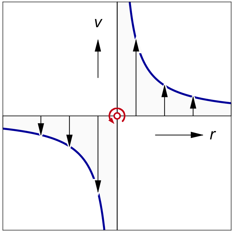
Figure 21.1 : The vertical velocity around a vortex.
When a parallel airstream flows across a vortex line, the circulation changes the flow into a locally curved flow. Immediately around the vortex line, the flow circles around the vortex line with infinite velocity. Since infinite velocities do not exist in real flows, in the real world the line of infinite velocity is always hidden inside a physical object.
The simplest such physical object is a rotating drum placed in a parallel flow. The rotating drum draws the air around it by its surface friction, matching the circumferential velocity of an ideal vortex at the drum surface. This arrangement is known as the Flettner rotor.
Remarkably, the same circulation pattern can be created without having a rotating object, just by the friction at the sharp trailing edge of a curved wing section. The wing trailing edge steers the local flow by the so-called Kutta condition.
Figure 21.2 shows the idea. The wing section bends air down, and creates lift as a reaction force. If we look at it from a reasonable distance the wing section can be modelled by a single vortex. This vortex lifts up the approaching air, and sends it down by exactly the same amount behind it. There is no net downwash, and the lift is exactly orthogonal to the undisturbed local velocity V. We will see later that a finite wing does have a net downwash, but it is not caused by the vortex around the lifting line.
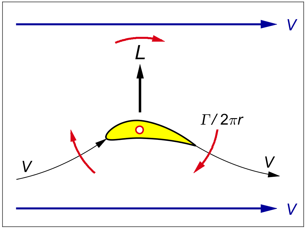
Figure 21.2 : The lift on a vortex placed in a parallel flow.
The force per unit length of vortex follows from the remarkably simple equation :
| (21.3) |
This is the aerodynamic equivalent of the Lorentz force on an electrical current in a magnetic field. The electrical current is the analog of the circulation, the wire carrying it is the analog of the vortex line, and the magnetic field in which the wire "lives" is the analog of the local airflow.
A single line vortex of constant strength Γ can be used to model both the lift and the downwash around a simplified wing. Figure 21.3 shows the vortex pattern. The single vortex line runs in a tuning fork shape called the "horseshoe vortex". The name was coined before it was realized that the transition between the legs is not rounded, but sharply kinked.
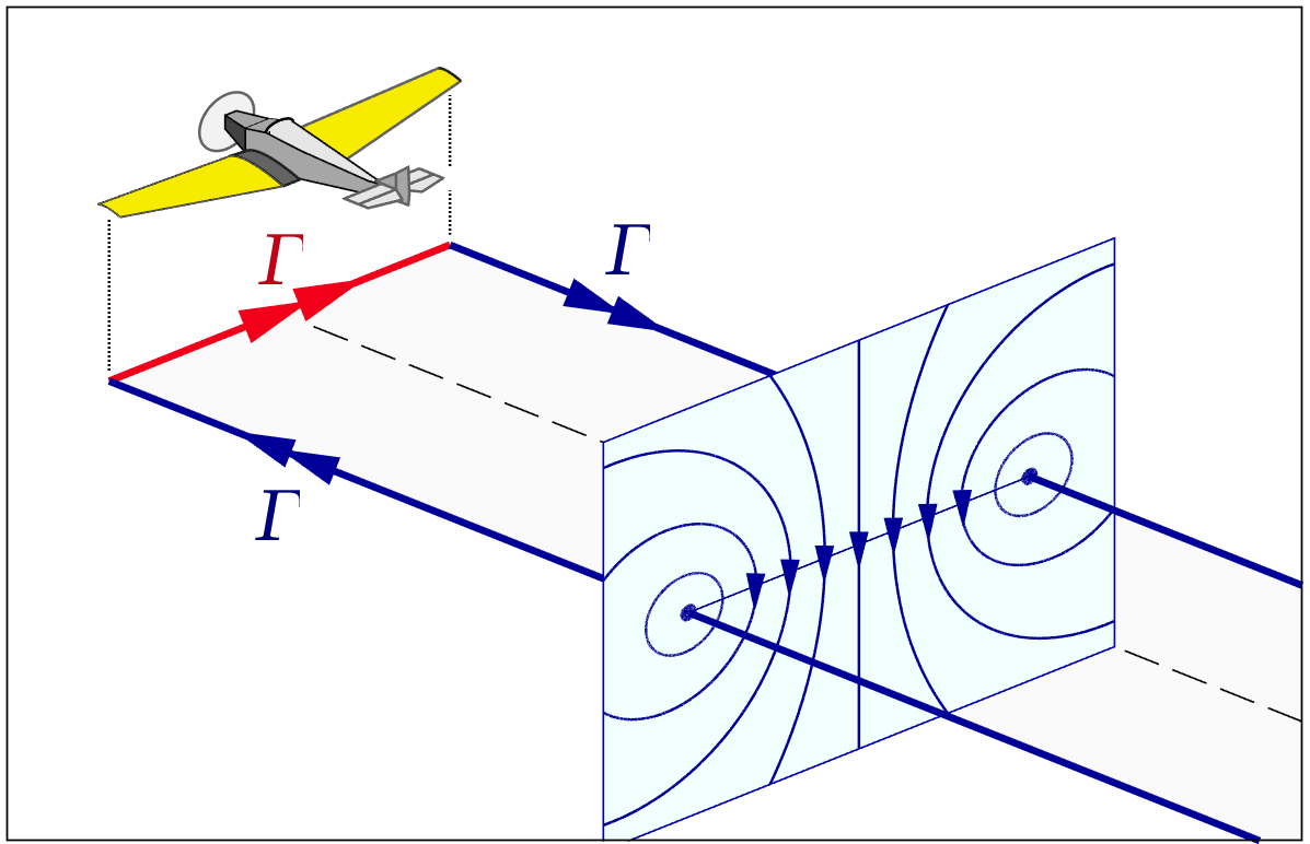
Figure 21.3 : The horseshoe vortex for a constant lifting line.
The physical wing is represented by the crosswind section of the vortex, shown in red in the picture. This crosswind vortex travels with the wing. Actually, it is continuously created by the wing. This section of the vortex is called the "bound vortex".
The span of a wing is traditionally denoted by b, not to be confused with our previous use of b for the local induction w / V. For an infinitesimal spanwise section db, the lift is :
| (21.4) |
The other two legs of the tuning fork are called "trailing vortices", colloquially known as "tip vortices". Viewed from the airplane, these tip vortices "trail" from the ends of the bound vortex. The wing tips leave these trails behind in the atmosphere like a snail leaves behind a stationary trace on the ground. Immediately after leaving the wing, these vortex trails simply float in the stationary atmosphere. They do not follow the airplane. The far end of the system is closed by another cross vortex left behind "at infinity", or at least very far away, where the aircraft took off.
Precisely because the trailing vortices have no self motion relative to the air around them, they are simply "written" in the exact path of the wing tips that created them. Floating free, they cannot exert a force on the air. The trailing vortices therefore do not cause lift. However, they do "cause", or at least describe, a circular motion of the air around each trailing vortex line as shown in the wake cross-section in figure 21.3.
The lift on the single bound vortex of a horseshoe vortex follows directly from (21.3) :
| (21.5) |
This is the only lift in the system. The trailing vortices do not contribute, because they drift with the flow.
The downwash far away from the wing is not affected by its bound vortex. The wing has moved infinitely far away from us by the time we start looking at the far wake. In the far wake, the only vortices nearby are the tip vortices, stretching infinitely far ahead and behind.
For measuring distances from the the center of the wing, we will use the spanwise coordinate x.
The effect of a single trailing vortex at a location xt on the downwash at a different spanwise location xw follows directly from the definition of the vortex in (21.2), at a distance r = xw − x t away from the vortex line :
| (21.6) |
Figure 21.4 shows the graph of the downwash from a single horseshoe ( two trailing vortices ) in the far wake.
Figure 21.4 : Lift and downwash for a single horseshoe vortex.
At the center of the far wake, both tip vortices stretch from ( almost ) minus to plus infinity. At the center of the wake, both tip vortices are at a distance of ½ b from the center. So by (21.2) the downwash at the center of the far wake from the two trailing vortices is :
| (21.7) |
The average downwash over the span is surprisingly difficult to calculate, due to the infinities at the tips.
The single horseshoe wing is physically impossible, due to the infinite downwash at the tips. Even if it were possible, it is also very inefficient.
Prandtl's co-worker Munk found early on that for a given total lift, the induced drag is at a minimum when the wing has constant downwash along the span. His reasoning was the same as the one used later by Betz to find the cos2 φ distribution for the optimal propeller.
But because the downwash of an arbitrary vortex pattern is not easy to invert, it took a while before he found the lift distribution which gives an even downwash. After "several attempts", to quote Prandtl, the corresponding lift distribution turned out to be a simple elliptical shape.
By a non-trivial integration, the following result was found for the downwash from an elliptical vortex distribution with a maximum circulation of Γo in the center of the wing :
TODO - mention Cauchy principal value, refer to Glauert integral further down.
| (21.8) |
We will define an average value for Γ over the span ( note the overbar symbol to indicate an average ). It equals the area of a half circle, which is π ⁄ 4 times that of the surrounding rectangle :
| (21.9) |
We can then write the constant downwash as :
| (21.10) |
The lift of the elliptical wing is quite easy to find. If we integrate (21.4) for an elliptical distribution of Γ, the area is that of an ellipse with a center height of Γo and an average value over the span of Γ :
| (21.11) |
Figure 21.5 shows the lift and downwash for the elliptical wing. The downwash in the middle is twice that of the flat lift case (21.7), for the same average Γ, i.e. for the same overall lift.
Figure 21.5 : Lift and downwash for the elliptical wing.
If we accept (21.10) for the downwash, then with (21.11) for the lift we can calculate the effective mass flow deflected by the wing, according to Newton's law (4.7) for the thrust of a propeller rewritten for the lift of a wing :
| (21.12) |
This is the well known result for an ideal ( elliptical ) wing : the deflected mass flow equals the flow through a circular tube, with the wing span as its horizontal centerline.
This result is normally offered in aerodynamics texts without proof, hidden in an expression involving the so-called "aspect ratio" A of the wing. In the form given here, the parallel with the circular tube accelerated by an ideal propeller in (5.2) is striking.
In texts on wings, (21.12) is usually given without proof, and in a noticeably different form.
First of all, it is written in terms of the deflection angle εi = v / V as induced at the lifting line, where it is exactly half the value of the far wake. This is a useful choice in the airplane wing, because the so-called "induced drag" directly results from the backward tilt of the lift vector by this angle.
Unfortunately, the equation is also usually given in terms of the so-called "wing aspect ratio" A ≡ b / c.
By definition,
This convention has given rise to the spurious impression that the wing aspect ratio is a governing factor in the induced drag of the wing, which it is not.
The governing factor is the span of the wing. For a given airspeed, lift and span, the induced drag is fixed. The aspect ratio will vary with the design lift coefficient, which determines the wing area, and hence the wing chord for a given span. The aspect ratio is a derived value. It has no direct influence on the induced drag.