VISCOUS LOSS
The classical way to handle viscous loss is the one shown in the previous chapter. The propeller is designed for optimal rotational loss (and later, for tip loss). The viscous loss is then calculated almost as an afterthought, and the outcome is accepted as a fact of life.
But this runs against the spirit of propeller optimization, which is to minimize the overall loss by scheduling the induction ( for constant marginal loss ).
Viscous optimization has been a wrinkle in the classical theory of propellers for a long time. Historically, Glauert already gave the proper solution, but his treatment is not complete, perhaps due to his untimely death in a freak accident. This incompleteness may be the reason why later texts fail to include it.
This chapter picks up Glauert's argument and takes it to its logical conclusion.
The literature is partly right : for normal propellers, not much efficiency is gained by doing a proper viscous optimization. But it is the proper thing to do, and it is not difficult after all. Perhaps more importantly, there is an unexpected side benefit in the shape of the blade.
Readers who use this text as their first introduction to propeller theory may wish to skip this chapter. Those looking for new material, or those who like to tie up loose ends, are encouraged to read it for their own personal enjoyment.
Figure 15.4 showed that for minimal viscous loss, all thrust should be concentrated on a paddle close to the hub at x = 1, for a 45° pitch angle. By contrast, figure 10.1 showed that the optimal momentum efficiency moves the thrust outboard towards the flattest pitch angles.
This difference creates a basic trade-off in blade shape design. We optimize this trade-off by our trusted method of constant marginal loss.
We are hoping to optimize the viscous marginal loss. But somewhat surprisingly, this is not how it works.
By (15.21), the viscous loss is directly proportional to the thrust. An increase of thrust will give an increase of loss, in the same proportion. This linear relationship makes the marginal loss ratio equal to the actual loss ratio, independent of the local induction. We will not be able to change the local viscous loss ratio by any optimization to the induction.
Formally, we can write (15.21) as :
| (16.1) |
Taking the derivative with respect to dT.V like in (9.1) gives :
| (16.2) |
This marginal loss is exactly the same as the actual local loss ratio (15.21). This is, of course, in the nature of any linear relationship.
Glauert used the simplified viscous drag ratio (15.16) here, but the ( almost ) exact equation (15.21) will give us simpler and more accurate results.
We combine (16.1) with the marginal momentum loss for an arbitrary ( but light loading ) induction b ( x ) in (9.4) :
| (16.3) |
The combined marginal loss will now depend on
b ( x )
through the momentum loss.
We will first look at the combined marginal loss
for the rotationally optimized propeller, without optimization
for the viscous loss.
This is an interesting reference case,
since most of the literature accepts this as the standard solution.
The b ( x ) for the rotationally optimal propeller was given by (10.8), and the resulting ( constant ) marginal momentum loss by (10.7). Substituting this into (16.3) yields :
| (16.4) |
This combined marginal loss is very similar to (16.1) which gave the actual local loss for the rotationally optimal propeller. The only difference is that the marginal momentum loss is exactly twice the local momentum loss, while the marginal viscous loss remains the same.
Figure 16.1 shows the result, with numerical values taken from our standard lightplane example. The graph is almost identical to figure 16.1, again with only the difference in the doubling of the momentum loss.
The combined marginal loss is not constant, and so this propeller is not optimal. Moving thrust from the tips to the region around x = 1 should improve the efficiency.
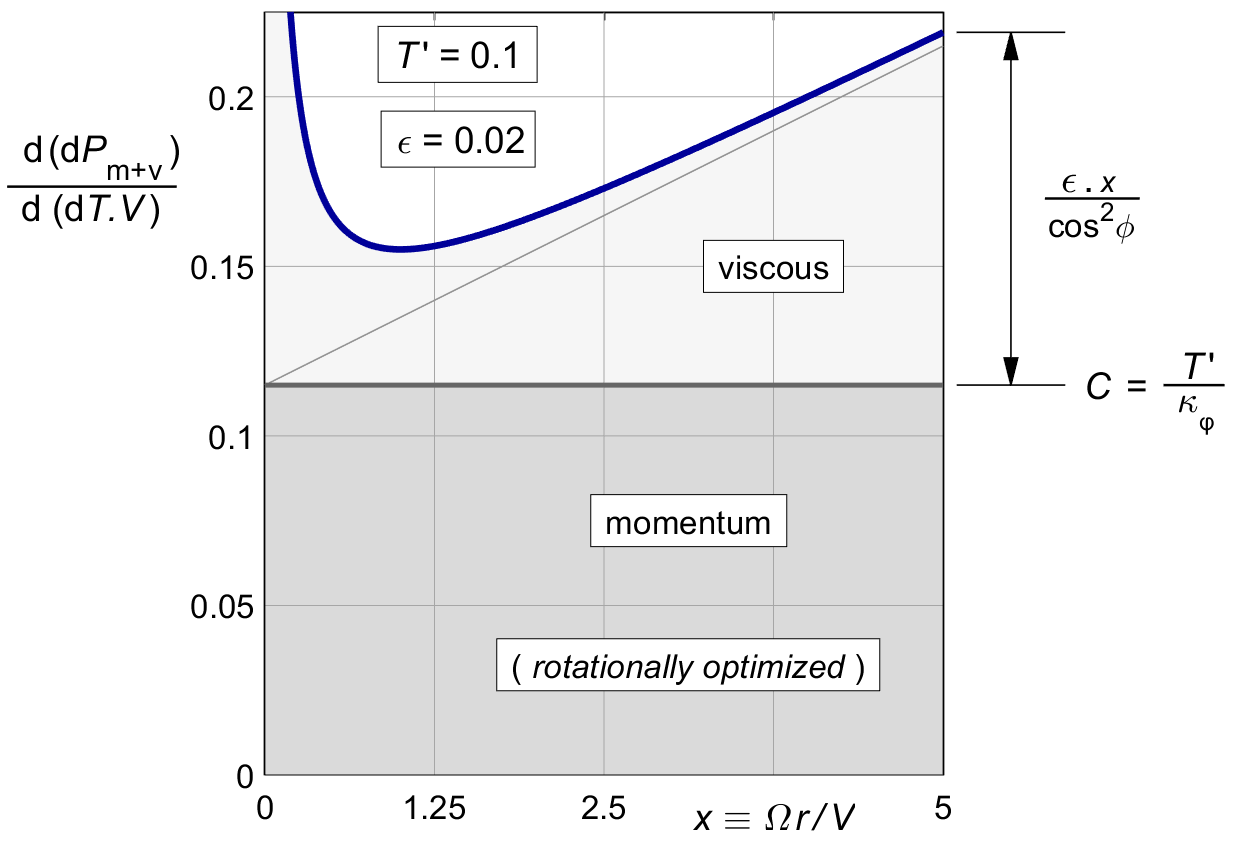
Figure 16.1 : The combined marginal loss (16.4) in the rotationally optimal propeller.
We are looking for a thrust distribution which makes the combined marginal loss constant along the blade. Since the new constant will have a different value than before, we will use a new letter A, instead of the C of (9.3). We will require :
| (16.5) |
With (16.3) this gives :
| (16.6) |
Since A is a constant, the combined optimal distribution becomes :
| (16.7) |
Relative to (9.5), the right hand term in x is new.
Glauert himself used the approximate μ ( x ) of (15.16), which yields :
| (16.8) |
This seems simpler than (16.7) at first sight, but when following it through the results are in fact more complex, so we will be using (16.7) from here on.
TODO Discuss Glauert's figure based on A.
The thrust is reduced to zero near X = A / ε. However, Glauert's figure is subtly misleading if we do not realize that for the same thrust, A is much larger than the C of (10.7). Therefore we will first express A in the design parameters.
We express A in terms of T ′, ε and X. Using the induction b ( x ) of (16.7) in the light loading integral (XXXXXXXXXX), the overall thrust is :
| (16.9) |
The left hand integral was called κφ in (10.5), and the primitive of 2 x2 is ⅔ x 3. Between the limits of x = 0 and x = X this gives ⅔ X 3, and so :
| (16.10) |
The marginal loss expressed in design parameters is therefore :
| (16.11) |
Substituting this into (16.7) gives the optimal b ( x ) in design parameters :
| (16.12) |
This is the equivalent of the induction (10.8) for optimal rotational loss, only this time including the viscous optimization. The original "amplitude" T ′ ⁄ κφ is increased by an additional ⅔ ε X ⁄ κφ.
This new fixed term makes up for the loss of thrust from the radius-dependent term ε . x. We will take a closer look at the shape of (16.12) in figure 16.4, but first we look at the two components of the marginal loss.
The marginal viscous loss is independent of b ( x ), but the marginal momentum loss is not. Substituting the b ( x ) of (16.7) into the marginal momentum loss (9.4) we have :
| (16.13) |
The left hand term is the constant marginal loss (16.11). The right hand term effectively subtracts the viscous marginal loss (16.2) from this, leaving a marginal momentum loss which is no longer a constant. The momentum loss by itself will no longer be optimal. Interestingly, the marginal loss is made constant by modifying the momentum term, not the viscous term.
Figure 16.2 shows the result. The optimization moves thrust towards the region of lower viscous loss near x = 1, as shown in figure 15.4. Increasing the thrust there means that we have to accept a momentum loss varying with the radius.
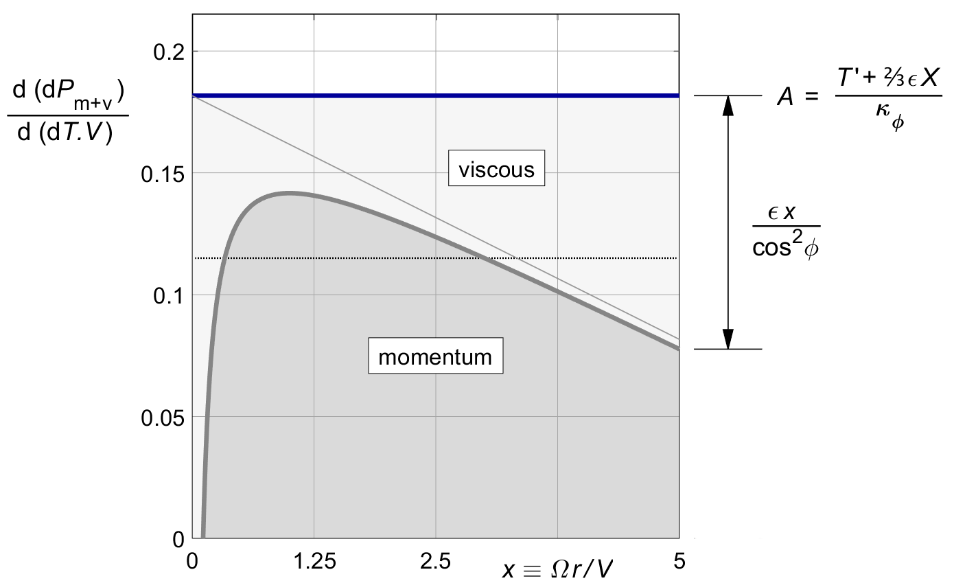
Figure 16.2 : Constant combined marginal loss, optimized by (16.3).
The combined marginal loss is constant along the blade. But unlike for the purely rotational optimum, the actual loss ratio itself is not. Substituting the combined optimum b( x ) of (16.12) into the generic momentum loss (8.4) gives :
| (16.14) |
The whole bracketed term together is a constant. It equals ½ A.
The first term within the brackets is the rotationally optimal momentum loss ratio (10.10).
The second term within the brackets is exactly half the average rotationally optimal viscous loss ratio of (16.6). These two terms are both constants along the span of the blade.
The third term, the only one outside the brackets, is not constant along the span. It varies with x both directly and via 1 ⁄ cos2 φ.
This local term is exactly half the viscous loss ratio of (15.21). With (16.14), the viscous loss has been split into two halves : a constant term depending only on X, and a varying term depending only on x.
Figure 16.3 shows the result for our standard lightplane example. Unlike the marginal loss, the actual loss is not constant along the blade. But compared to figure 16.1, the difference with a constant local loss ratio has approximately been halved.
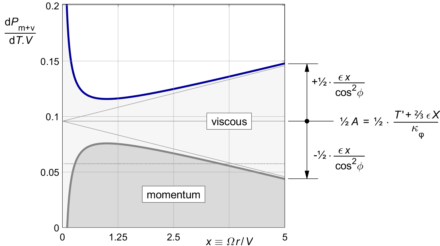
Figure 16.3 : Combined local loss, optimized by (16.3).
Figure 16.4 gives the shape of the optimal induction distribution according to (16.12), for our standard lightplane example of T ′ = 0.1, for viscous friction values of ε = 0 and ε = 0.02. The zero-friction case of figure 11.1 is shown in red. There is a cross-over at 0.7*thinsp;R, and this is easier understood by collecting terms in T ′ and in ε (16.12) :
| (16.15) |
The left hand term provides all the thrust. It is identical to the purely rotational distribution (10.8). Its contribution is directly proportional to T ′.
The bracketed term on the right hand side is the viscous correction. It does not affect the thrust at all. It is proportional to ε, and it vanishes for ε = 0. This term will always become zero at approximately the following radius :
| (16.16) |
This is just over two thirds of the prop radius,
say at 0.7 R.
The location makes sense.
The net thrust of the correction term is zero,
and since
The tip value of the distribution is :
| (16.17) |
For larger X the tip value of the distribution is well approximately by :
| (16.18) |
The tip chord vanishes for T ′ < ⅓ ε . X, and the blade will get a sharp point there.
In general, ε . X ⁄ T ′ is the shape factor for the viscous correction. The correction is most pronounced for lightly loaded propellers of high tip speed ratio, and for high values of ε. The change in shape of the thrust distribution is obvious.
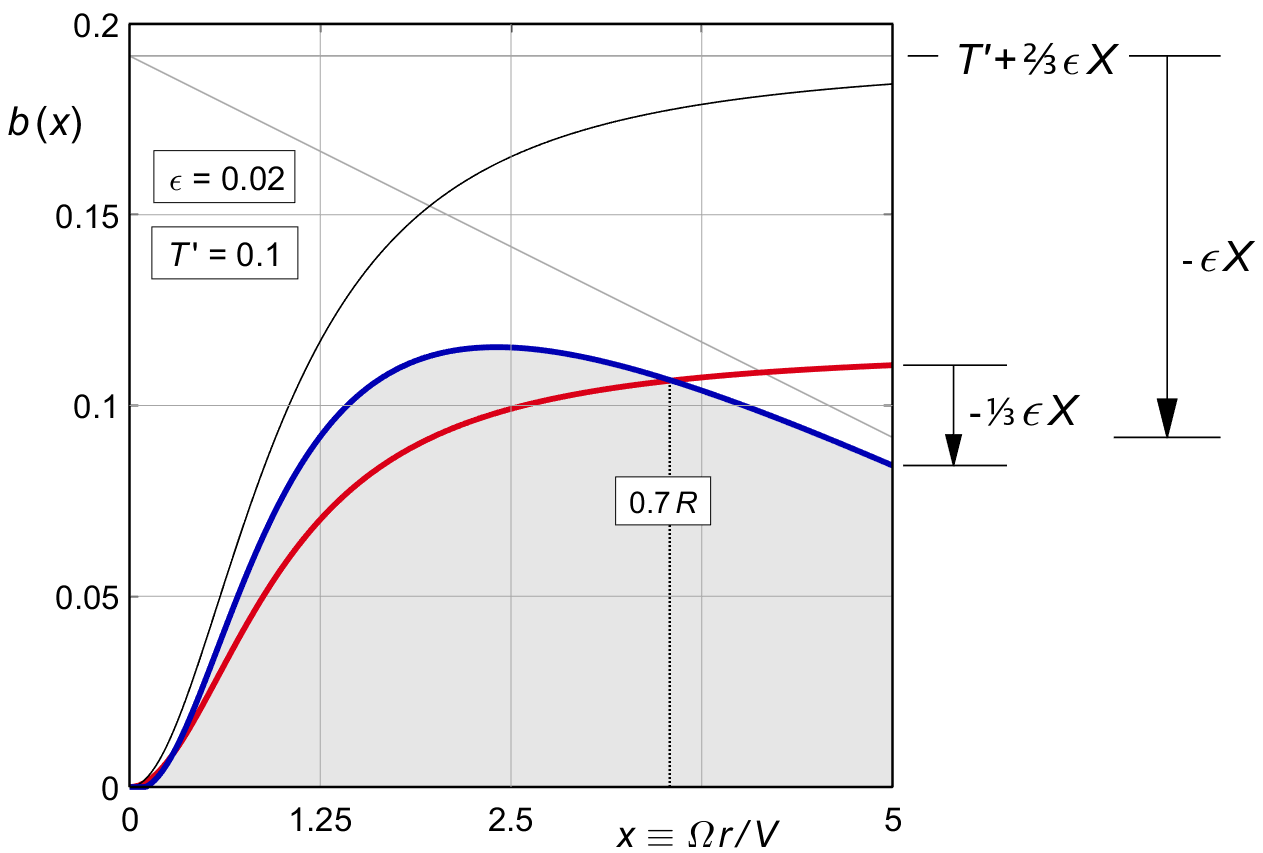
Figure 16.4 : Thrust distribution after viscous optimization (16.12).
T′ = 0.1. Red : ε = 0. Blue : ε = 0.02.
Equation (16.7) gave the combined overall momentum and viscous loss of a propeller optimized only for rotation. We now calculate the improvement when adding the viscous optimization.
We expect an increase in the momentum loss, because the distribution will no longer be fully optimized for momentum loss. In turn, we expect a stronger improvement in the viscous loss. The sum of the two losses is going to decrease. We will calculate the improvement in the viscous loss first.
Equation (15.21 XXXXXX TBC ) gave the viscous loss on a ring, for an arbitrary ( light loading ) induction b ( x ).
Substituting the optimal b ( x ) of (16.12), some of the cos2φ terms will cancel :
| (16.19) |
〖P_v〗^' = 1 /X^2 ∫_0^(X )▒〖( (T ^'.ϵ.x)/κ_ϕ + (⅔ .ϵ^2.X. x)/κϕ - (ϵ^2.x^2)/(cos^2 ϕ) ) .2 x .dx〗 (16.19)
The first term, together with the 2 x outside the brackets, yields an integral of 2 x2 with primitive ⅔2 x3. The result equals the non-optimized loss for a rotationally optimal propeller, (****).
The second term has the same order of x, but with a different constant.
In the third term, (2.8) changes the x2 / cos2 φ term to 1 + x 2. Together with the 2 x outside the brackets, the primitive of this term is x 2 + ¼ x 4.
The overall integral becomes :
| (16.20) |
Collecting terms, the non-dimensional loss ratio as in (3.9) is :
〖P_v〗^'/T^' = ⅔ (ϵ .X)/κ_ϕ - ϵ^2/(T ^' ) .(1+X^2.(½ -(4/9)/(〖 κ〗_ ϕ ))) (16.21)
The left hand term is the viscous loss ratio of the rotationally optimal propeller of (16.6). The right hand term in is the decrease of the viscous loss ratio due to the viscous optimization. We will see below that exactly half of this gain is lost to an increase of the momentum loss ratio.
TBW.