ROTATION
So far, we discussed a purely axial momentum theory. But the blades of a propeller also cause a rotation of the wake, and this causes extra momentum loss. This extra loss is a factor on the axial loss. We could call it the rotational overhead. The rotational overhead depends exclusively on the local pitch angle φ.
This chapter discusses the rotational factor without regard to tip loss. We will see later that the analysis holds without change for that case as well.
We will first calculate the rotational loss, and then optimize it.
Chapter 6 subdivided the prop disk into a nested assembly of independent, thin-walled flow tubes, cutting up the prop disk plane into concentric rings. We consider the conditions in one of these rings.
Figure 2.3 showed how the blades meet the air at a local aerodynamic pitch angle φ. By the very definition of lift, the blade lift is orthogonal to the local velocity vector W. The local lift dL is tilted relative to the direction of flight by the same pitch angle.
Figure 8.1 shows the force diagram for a blade element.
Figure 8.1 : Force diagram for a ring.
The thrust is the forward component of the lift :
| (8.1) |
In the actuator disk, the thrust pointed straight to the rear, causing a purely axial induced velocity v at the prop disk. With the lift tilted by the angle φ, by Newton's law of action and reaction the velocity increment is tilted by the local pitch angle φ .
We will call the induced velocity at the prop disk v ′. Figure 8.2 shows the velocity diagram.
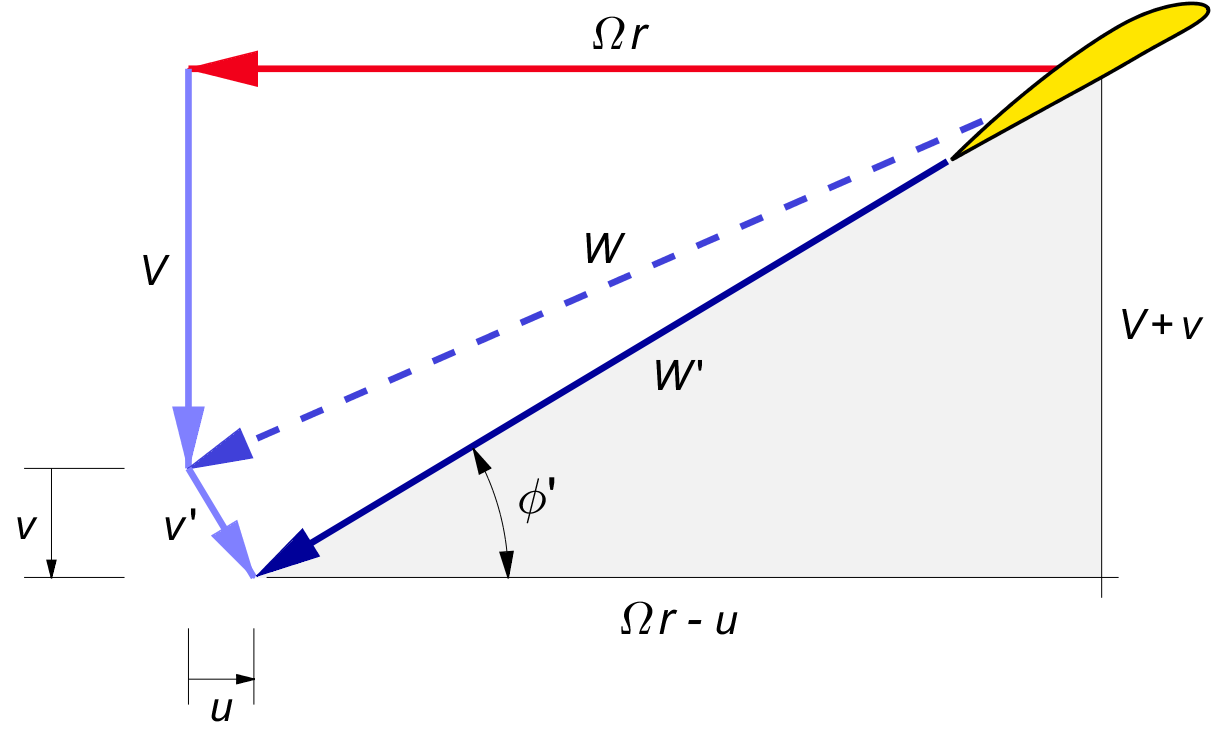
Figure 8.2 : Velocity diagram for a ring.
The induced velocity is orthogonal to the local blade velocity W ′. Therefore, v ′ is tilted relative to the flying velocity V.
In lightly loaded propellers, the induced velocity v ′ is much smaller than the blade relative wind W ′. This makes W and W ′ almost the same length, and v ′ nearly orthogonal to both. The axial component of the induced velocity at the prop disk is v.
We will call the rotational component u. We approximate φ ′ by φ, which is in keeping with the light loading assumption. From the diagram we have :
| (8.2) |
and so :
| (8.3) |
The tangential component is :
| (8.4) |
The induction v ′ is at right angles to W. Therefore the induction gives almost no change in length from the nominal wind speed W to the actual wind speed W ′. There is a change in angle, however.
The induction v ′ changes the effective local pitch angle. We can extend the vector V in figure 8.2 straight down by a length of v ′ / cos φ to meet the extension of W ′. This gives the following tangent of φ ′ :
| (8.5) |
With tan φ = V / Ω r and v / V = ½ b as usual, this yields :
| (8.6) |
When the axial induction b is relatively large, it is more exact to replace the angle φ by φ ′ in some of the calculations, but the differences are not large.
The sideways induced velocity u will change the direction of the local wind velocity V in in figure 8.2 by an angle ψ ( Greek letter "psi" ). Using (8.4) for u, the tangent of this so-called swirl angle is :
| (8.7) |
Further downstream, the velocities will be w and V + w. With w / V ≡ b from (4.2), the swirl angle in the far wake will be :
| (8.8) |
The swirl angle ψ is smaller than the pitch angle φ by a factor of roughly b. For normal, “lightly loaded” values of b ≪ 1, the swirl angle is at most a few degrees.
The swirl angle gives an angle of attack to the fin of single engine aircraft. This is the reason why aircraft with right hand turning propellers veer to the left when power is applied, an effect often ascribed to "torque". Many light aircraft have fins with a built-in offset to accommodate the average swirl angle, but this does not undo the effects of changing power.
We will briefly discuss the options of counterrotation and swirl recovery in chapter 15, but without such special measures the propeller leaves behind the rotation of figure 8.2, and this rotation is lost to the atmosphere.