AXIAL MOMENTUM
Much of propeller theory is based on the idea that a propeller influences only the air passing through the prop disk, and that it influences none of the air outside it. This model is surprisingly accurate, but it is far from obvious. The real justification comes from a vortex view of the flow. This view is given much later, in the section on vortex theory. For now it is best to accept the actuator disk as a working model.
The ideal propeller acts like an imaginary disk of frontal area
Figure 4.1 shows an actuator disk, halfway the length of a solid streamline tube. Later chapters will fill in the disk with more detail.
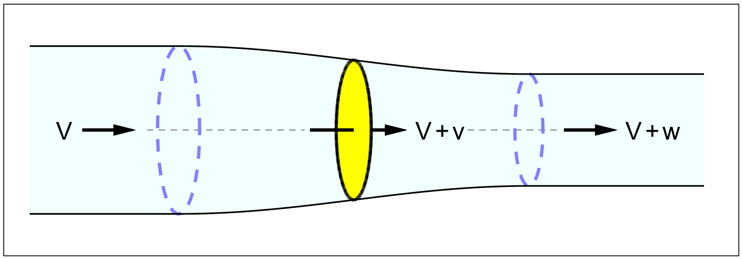
Figure 2.1 : Actuator disk and flow tube.
In the stationary frame of reference, the disk moves forward through the air at the flying speed. It exerts a small push force to the rear on the air passing through it. The acceleration of the air ( at almost constant density ) makes the tube contract a little. The contraction of the tube moves forward with the disk, in a motion like swallowing. The disadvantage of using this frame of reference is that the movement of the air at a given viewpoint is time-varying as the disk passes by the observer. The equations are much simpler if the observer moves alongside with the disk.
Relative to us, the disk will then be stationary, and the whole atmosphere will be flowing by. We might call this the "wind tunnel view", or the view from the cockpit. The relative motion is the same as for a propeller moving through a stationary atmosphere, but now the air at a given point is flowing by continuously at the same speed. The air far ahead of the propeller is the undisturbed atmosphere "flowing towards" the actuator disk.
Far behind the actuator disk, the air flows at a slightly increased velocity through the slightly contracted flow tube. Since the walls of the flow tube far downstream of the disk are straight, there can be no sideways pressure gradient. Any sideways pressure on the air would curve the flow locally. Therefore the pressure in the "far wake" must be identical to the atmospheric pressure. The air in the far wake flows straight to the rear at a constant velocity, "induced" by the propeller.
The actuator disk ( like a wing ) only creates a pressure step. The volume flow through the frontal area is the same just ahead of and just aft of the disk, and so the velocity cannot instantaneously change there. The pressure makes no difference to the volume, because air is practically "incompressible", in the sense that the aerodynamic pressures are so small relative to the massive static pressure from the weight of the atmosphere above us, that the air hardly changes in density due to ( subsonic ) flow conditions.
The pressure field ahead of, and aft of the disk induces a gradual acceleration of the air to the rear. Because of the constant volume, the downwind tube has a slightly smaller cross-section than the upwind tube. All of the acceleration, and therefore all of the contraction of the tube, takes place over a short distance ahead and aft of the actuator disk. The tube walls are curved in an S-curve over this relatively short distance.
We will call the axial velocity increase reached at the disk v, and the final velocity increase far behind the propeller w. We will use the letters a and b for the non-dimensional versions of these so-called "induction ratios" : the first one locally at the disk, and the other one in the "far wake" :
| (4.1) |
| (4.2) |
One of Newton's laws asserts that action equals reaction. An object can only push itself forward by pushing something else back. If that something else is not infinitely heavy, it will start moving in the opposite direction, as anyone can testify who has ever tried stepping ashore from a small boat. The mechanism applies equally to air.
A propeller pushing an airplane forward will have to push some quantity of air to the rear. This will give that air a velocity increase. Newton’s second law states that the force needed to accelerate a mass is proportional to the mass times its acceleration :
| (4.3) |
This is not the a of (4.1), but the momentary acceleration. Acceleration is the change of velocity per second. We can also write (4.3) as :
| (4.4) |
The raised dot ● is Newton's symbol for "per second". A lesser known version of the same law is :
| (4.5) |
Here the force equals the change in the "quantity of motion" ( m . v ), which is also known as the "momentum".
The momentum can change by a change of mass per second, just as well as by a change of velocity per second. Instead of accelerating the same mass to an ever higher velocity, we can take a new mass m● every second, and give it the same velocity increase v every time.
For example, we can exert a forward force on ourselves by throwing a snowball of mass m to the rear every second, or by squirting a continuous mass flow of water m● out of a fire hose at a constant velocity v.
We can write (4.5) as :
| (4.6) |
We use version (4.6) of Newton's law for the propeller.
Let us say that each second an air mass m● flows through the prop disk. From figure 4.1, this mass gets a velocity increase from V to V+w, i.e. a net velocity increase of w. The propeller exerts a constant rearward force F on the flow, and by Newton's first law receives an equal but opposite forward reaction force which we will call the thrust T. Then Newton's second law for a propeller is :
| (4.7) |
This is the basis of what is called the "momentum theory" of the propeller. With the definition for b in (4.2) we can also write :
| (4.8) |
We now look at the power. First we calculate the power at the prop disk. With (3.5) for the net power and (4.7) or (4.8) for the thrust we have :
| (4.9) |
From figure 4.1, the propeller works in a local flow of increased velocity of its own making, ( V + v ). On this flow, the thrust of the propeller needs to exert the following power, since power is force times velocity :
| (4.10) |
The local momentum loss ( actually, the gross power increase ) is :
| (4.11) |
Note that Pm is not the total momentum power, but only the extra power due to the induction velocity v, on top of the power T . V needed to drive the airplane forward at its flying velocity V.
The momentum loss ratio is the ratio between (4.11) and (4.9) :
| (4.12) |
By (3.9), the non-dimensional form of this ratio is :
| (4.13) |
The propulsive efficiency is the ratio between net output power and the gross input power. It does not depend on the mass flow, only on the induction ratio a.
From (3.10), the momentum efficiency at the prop disk is :
| (4.14) |
The wake velocity w = b . V dropped out of the momentum loss ratio (4.12) when dividing (4.9) by (4.10). But the wake velocity is interesting in its own right, so we derive it here from an energy argument. The propeller leaves behind a velocity w, and therefore also a kinetic energy, in the atmosphere. The equation for kinetic energy is ½m v2 , but in this case the velocity is w, and the mass is m● per second.
Energy per second is the definition of a power, and so the kinetic energy lost to the wake represents the following power :
| (4.15) |
With the net power (4.9), we have an alternative expression for the loss ratio :
| (4.16) |
The mass flow m● drops out of this ratio like it did in (4.12). Once again, the efficiency does not depend on the mass flow. This time it only depends on the far wake induction ratio b. By (3.9), the non-dimensional form yields :
| (4.17) |
From (3.10), the far wake efficiency is :
| (4.18) |
We now have two ways of calculating the momentum loss ratio and they must be equal, because the propeller can have only one efficiency, whichever way you calculate it.
Equating (4.13) to (4.17), or (4.14) to (4.18), we have :
| (4.19) |
The flow towards the disk and the flow away from it are anti-symmetrical. Air accelerates towards the oncoming propeller, as if it is "sucked in", and then accelerates by the same amount aft of it, as if it is "pushed off". The propeller disk itself is exactly halfway this process.
There is a direct parallel with the downwash of a wing, which we will discuss in a later chapter on vortex theory.