INTRODUCTION
Before going into the theory, we need to set a few definitions. Readers who are already familiar with the terminology can skip this chapter on a first reading, and refer back to it later when necessary.
A propeller blade is a rotating wing. Like in a wing, the width of the blade is called the "chord". The chord is measured in the nominal streamwise direction. The propeller has a diameter D, and a maximum radius R which equals D / 2. The distance from the root of the blade is measured by the local radius r. A small lengthwise strip dr of the blade is called a "blade element".
Figure 2.1 shows some of these definitions.
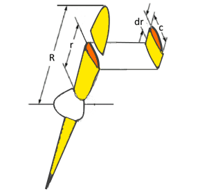
Figure 2.1 : Blade element.
A propeller's pitch is its forward movement during a full revolution of the prop shaft. The result of the forward and rotational motion of a blade element is a spiral path.
Figure 2.2 shows the path of a blade element at radius r.
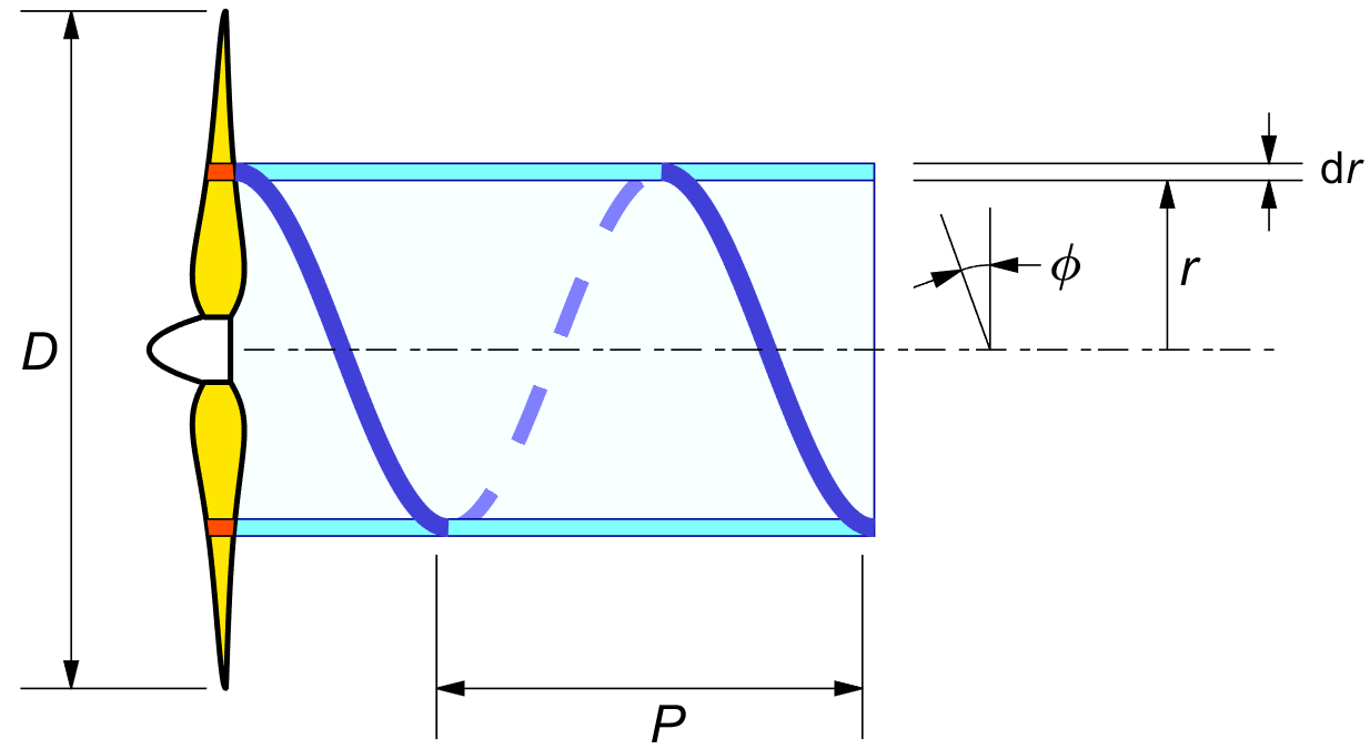
Figure 2.2 : Pitch P and pitch angle φ.
The forward motion for one revolution is P and the circumferential motion is 2 π r, and so the slope of the local pitch angle φ equals P over 2 π r :
| (2.1) |
Most propellers are designed for a certain flying velocity and shaft RPM. Expressing the velocity V in meters per second and the RPM in revolutions per second immediately gives the forward travel in meters per propeller revolution, and this is the aerodynamic pitch of the propeller.
A fixed pitch propeller will often be manufactured with the same "geometrical pitch" all along the blade. The geometrical pitch angle at any radius follows from (2.1), giving the blade its characteristic twisted appearance.
Figure 2.2 shows the blade element "living" inside a thin-walled tube of air between the radii r and r + dr.
Much of classical propeller theory assumes that the blade elements influence only the air between the walls of this imaginary tube, and not the air inside r or outside r + dr. We will revisit this rather bold assumption later.
In flight, the forward speed and the rate of rotation will generally not match the geometrical pitch of the propeller.
The actual aerodynamic pitch angle will be in line with the blade element
velocity diagram of figure 2.3.
The blade circumferential speed Ω r is the product of
the angular velocity Ω of the propeller
The actual local velocities V and Ω r are modified a little by the blade's own lift, inducing a downwash at the blade element. This is part of the theory.
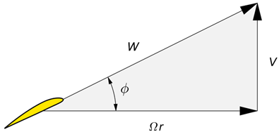
Figure 2.3 : Blade element velocity diagram.
The propeller literature supports a wide variety of symbols. Some can even have opposite meanings. Airplane texts generally use the letter λ for the "tip advance ratio" λ ≡ V / Ω R, while the wind turbine community uses the inverse convention, the "tip speed ratio" λ ≡ Ω R / V.
The difference does make sense. A wind turbine starts from zero RPM, and an airplane starts from zero forward velocity. In both cases we wish to avoid a division by zero in the starting condition, so we do not want a zero in the denominator.
It is unfortunate in both cases that
the lowercase letter λ is used
for a blade tip condition, since another convention is
that local values
We will avoid the letter λ altogether.
Following Glauert's
convention ( at least in part of his work ),
we denote the local speed ratio Ω r / V
by the small letter x.
By the capital letter convention we call its tip value X.
This makes X equal to the λ of the wind turbine world,
and to the
Using X instead of λ c.q. 1 / λ is a bit unusual, but it works out quite well in the equations.
| (2.2) |
| (2.3) |
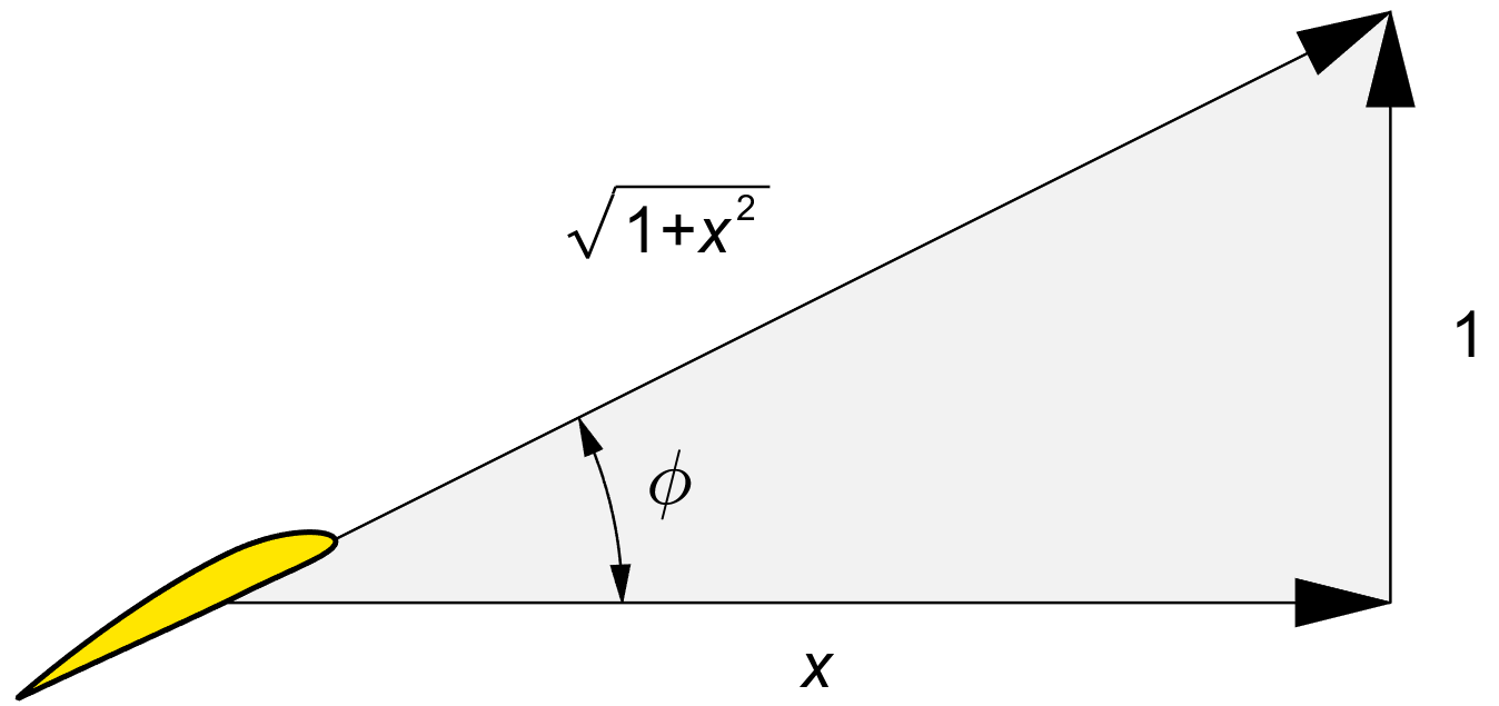
Figure 2.4 : The local speed ratio x.
Figure 2.4 gives the velocity diagram in terms of the local speed ratio x. At the tip, we use the capital letter X. The figure shows by inspection :
| (2.4) |
| (2.5) |
| (2.6) |
Another relation which comes up frequently in the theory is :
| (2.7) |
This also means ( directly, or by trigonometry ) :
| (2.8) |
We will freely use a mixture of function arguments φ and x, on the understanding that they are easily converted into each other. In particular, the cos2 φ term comes up very frequently and is more easily recognized when it is expressed in φ rather than in x.
The ratio V / Ω is the forward progression of the propeller for one radian of rotation. It has the dimension of a length. We will call this "typical length" U :
| (2.9) |
The non-dimensional speed ratio x equals the dimensional radius r, divided by this standard length. We can rewrite (2.2) and (2.3) as :
| (2.10) |
| (2.11) |
At the non-dimensional radius x = 1, the pitch angle is 45° and tan φ = 1.
If two propellers have the same tip speed ratio X,
then they have the same tip pitch angle
φ tip
As a corollary, we have :
| (2.12) |