Most of the literature on classical haptics tacitly assumes impedance control as a paradigm when discussing device design, stability, rendering and software architecture. This sometimes leads to conclusions presented as generic, which are completely in error for admittance controlled devices.
We will briefly discuss impedance control here so we make the distinction between what is actually generic, and what is specific to impedance control. Readers purely interested in admittance control can skip this chapter.
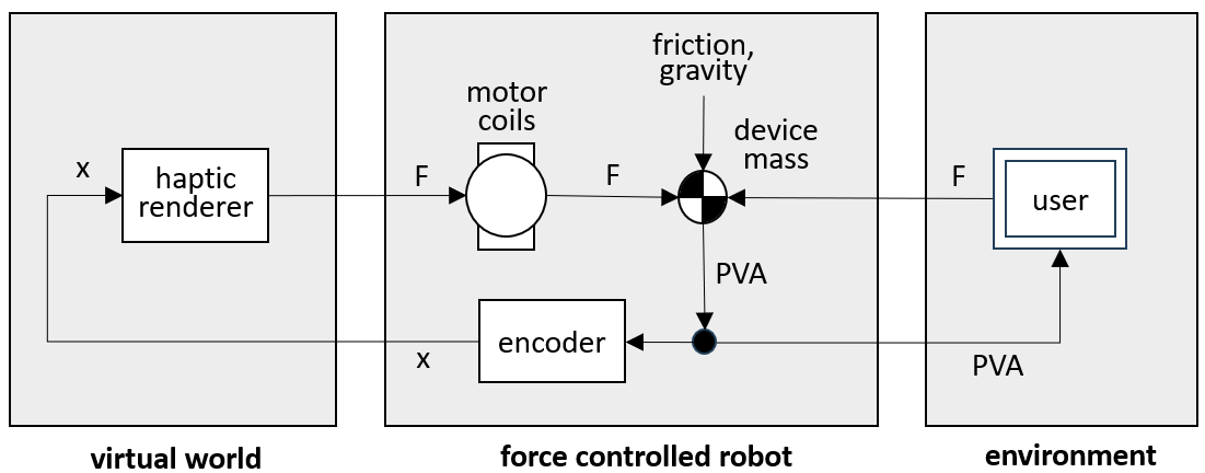
The assumption in the left hand figure 4.1 was that the user inputs a desired movement of the device and perceives the force needed to do that. Due to the small device mass and hopefully small friction, the user will hardly notice the dynamics of the device itself, and "feel" the force from the haptic renderer as though the device were transparent to it.
The device mass itself is usually neglected in the analysis. For easier comparison to admittance control however, the impedance control block diagram of figure 6.1 below includes the physical device mass. We do not assume that the user directly inputs a displacement. Instead, the user moves the device mass by a hand force. This force adds to the motor force and the friction force. Together they control the passive device mass according to Newton's law. The haptic renderer and the "user" both react to a displacement by a force. From the device's point of view, they are both "impedances".
When an impedance controlled device is switched off, the driving force from the motor is zero. The user's hand, plus the device friction and gravity forces, accelerate the device mass.
This is the state in which impedance controlled devices simulate free motion, “in free air”. Impedance controlled devices are therefore normally designed to have mechanically low mass and low friction. A small desktop device will have an effective end effector mass of 20 grams, i.e. 0.02 kg , and an effective friction force of 5 grams, i.e. 0.05 N.
The "control gain" K in figure 5.1, from physical device position to motor force, is zero since the motor force is always zero. The loop is simply not closed.
The end effector can be held against a hard physical surface and it will make no difference in the motor torque. Hard physical surfaces do not present a stability problem to an impedance controlled device. This is a major advantage of impedance control over admittance control.
In a passive device, the user will feel the weight of the end effector and the mechanism behind it. While these are usually light in weight, this may become a problem if the end effector has a powered gripper, or a similarly heavy appendage.
It is possible to add a motor force compensating for the weight, to make the end effector "float", but in practice the linkage forces are very dependent on the pose of the mechanism, since each link contributes to the bias force at the end effector in its own way. Imperfect balancing will cause the end effector to float up or down, or sideways which is even more disturbing. This is one more reason why the end effector in an impedance controlled device is preferably kept light.
Friction compensation is nearly impossible in an impedance controlled device, because at standstill there is no way of telling the intention of the user : the device cannot know in which direction the user will wish to move next.
Once in motion, a "helping" motor force in the direction of motion can be added, but the transition from hard stiction to active friction compensation will always be felt. A later chapter will go more deeply into the psychophysics of friction.
The practical solution is to design impedance controlled devices for low friction between the motor and the end effector. In practice, this rules out high gearing. Impedance controlled devices typically have light, low-friction cable quadrant drives ( "capstan drives" ) with maximum transmission ratios of 15 : 1. This limits the maximum rendered force to the order of 1 N ( 0.1 kgf ), which limits the use to lightweight and small applications.
Once the impedance controlled device is switched on, it can "display" virtual forces to the user. A haptic rendering software model will compute virtual forces acting on the stylus in a virtual world, and the controller will command these forces directly to the motor. Maybe the simplest effect that a haptic device can render is a virtual spring ( or, if the spring is one-sided, a virtual wall ). Unlike the admittance controller discussed later, the impedance controller has a problem in rendering such stiff virtual springs. A spring returns this force when stretched :
| (6.1) |
Here F is the spring force, x is the extension of the spring, v is the extension velocity, K is the spring stiffness, and D is the damping. When a mass is attached to the spring, then from Newton's law F = m . a, the dynamic equation is :
| (6.2) |
There is a standard solution for this equation. From mechanics texts, we know that if the mass is pulled back on the spring and then released, it will oscillate back and forth with the following frequency :
| (6.3) |
This is the undamped frequency. With damping present, there will be a small correction, but (6.3) is the resonance frequency of an undamped spring-mass system.
One way of looking at the stability of this system is to think of a loop with a small delay. The spring force simulated by the motor, based on the measured position, will lag the ideal model value a bit. In an oscillation, the spring force will persist a while on the return path, and during the zero crossing. This accelerates the return velocity. A force which increases a velocity is the opposite of a damping. Any mechanical damping that may have been present will soon be cancelled, and the oscillation will diverge and become unstable.
The device is trying to emulate a pure undamped spring acting on the physical device mass, and it cannot live up to this ambition beyond a certain frequency. We can cast the same argument in the form of the closed loop control equations of chapter 5.
The device G in figure 5.1 is a small robot which turns an input force u into an output y. We will call the output x here, because it is a position. With the Laplace variable s meaning “take the derivative”, the velocity is v = x . s, and the acceleration becomes a = v . s = x . s2.
Then Newton’s law F = m . a becomes F = m . x . s2, and from this x / F = 1 / m . s2, with m the device mass. The system G has just become a double integrator :
| (6.4) |
The stiffness K converts the output position x into a desired input force to G :
| (6.5) |
The closed loop transfer of (5.5) becomes :
| (6.6) |
From (5.9) the system is unstable if K . G = -1, which yields here :
| (6.7) |
Recalling from section 5.8 that s = - j . ω and therefore s2 = − ω2, we have :
| (6.8) |
This is the same result as in (6.3).
Another way to get the same result is by directly solving for the frequency where the denominator m . s2 + K of the closed loop transfer function (6.6) becomes zero. These zeros of the denominator are called the "poles" of the closed loop system.
TBW Numerical example
Impedance control device damping - passive or active. Unusual to have a high quality velocity sensing. Viscous dampers, best without a flywheel because you will feel the extra mass.
The position and velocity of the virtual model in impedance control is obtained from the device. The velocity is obtained by differencing the encoder signal. The encoder position has discrete steps ( it is "quantized" ). Differencing makes for a very noisy signal. This can be smoothed by realtime filtering, but this comes at the cost of large delays which impact stability.
As a result, haptic renderers for impedance controlled devices usually do not implement virtual damping at all. They rely completely on the device Coulomb friction for damping.
Differencing increases position noise by 1 / T as opposed to decreasing force sensor noise by 1 / T on admittance control ( due to the virtual mass integration ).
TBW. Confusing. Useful for stability. Seems limited to twice the device mass.
Due to the usual lack of active velocity feedback, large scale motions of im-pedance controlled devices tend to be poorly damped. Position control of the device ( moving it to a specific location, especially without a user holding the end effector ) is normally not possible without undue jerks and oscillations.