An aircraft is, among other things, two weathervanes : one acting in the symmetrical up-down direction ( leading to the "short period" mode ), and one acting in the left-right direction ( leading to the "Dutch roll" mode ).
This section will first discuss the weathervane, and then its close relative the arrow, or dart. This will lay the groundwork for the discussion of these oscillating airplane modes.
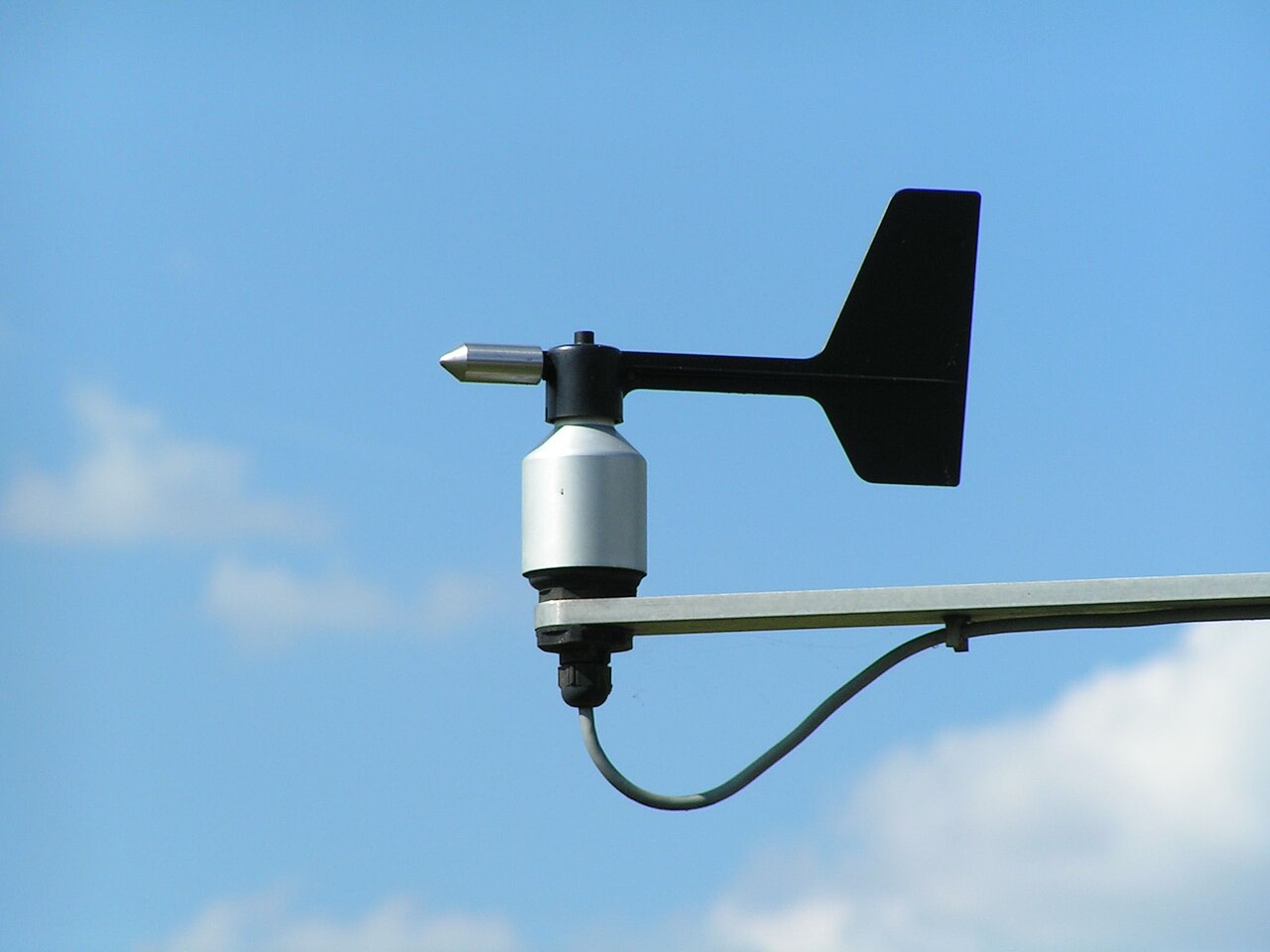
We will start with the simple weathervane or weathercock, as found on church steeples. Modern versions in weather stations and on sailing yachts often take the shape of a simple straight fin on a pivoting rod, see figure 1.
Figure 1 : Weathervane
Let us call the the distance between the fin and the pivot axis l f, the fin area S f, and the wind velocity V.
The lift ( side ) force on the fin follows the normal equation for the lift on a wing :
| (1) |
But what is CL ? That depends on the so-called "angle of attack" α of the wing. This is the angle between the wing chord and the local "undisturbed" flow, i.e. the local flow direction before the wing was present.
Potential theory tells us that the lift coefficient is proportional to the wing angle of attack as follows :
| (2) |
The factor of 2π is for a 2D wing section, but for a finite wing it is close enough.
Now let us call the angle between the fin and the undisturbed wind θ
| (3) |
Suppose the moment of inertia of the rod-plus-vane about the axis of rotation is Ixx.
By Newton's law and with α = θ, the angular acceleration about the pivot axis will be :
| (4) |
In words, the second derivative for the angle θ with respect to time is directly proportional to the angle itself. The minus sign represents the fact that the torque tends to reduce θ. This is the equation of a pendulum, or a linear oscillator, with frequency of oscillation ( squared, and in rad/s ) :
| (5) |
Note that this particular ω is not the angular rate of rotation of the vane. We will call that angular rate q later.
The oscillation frequency ω will go up with the wind speed, and with the square root of the fin area S f.
The effect of arm length is a bit less clear cut, because the moment of inertia Ixx will often increase with the square of l f.
The wind vane is often mass balanced to have the center of gravity ( CG ) on the pivot axis. This gives less bending moment in the bearing and more importantly ( especially on the tip of the mast of a sailing yacht ), shaking the vane bearing will not influence the vane angle.
We notice in passing that if the CG is on the pivot axis, then for the CG to stay in place laterally on a fixed pivot, the bearing force will have to be the exact opposite of the side lift on the fin at all times.
Now suppose that we leave out the fixed pivot. How does this change the dynamics of the weathervane ? In effect, this changes the weathervane into a free flying arrow, or dart. Figure 2 shows such a dart. The definitions are the same as for the weathervane, but the pivot axis is replaced by the center of gravity, these days often called the center of mass ( COM ) of the dart.
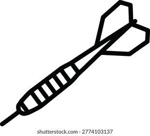
Figure 2 : Dart schematic
With the pivot point no longer fixed, we have two new degrees of freedom ( DOF's ). The COM can now move freely both in the direction of flight, and at right angles to it. We will only look at the direction at right angles to the wind. In the picture this is the up / down direction .
Until we consider damping, the moment equation (3) is not affected by leaving the COM free to move laterally. There is, however an added sideways acceleration of the COM, because the pivot no longer compensates for the lift force on the fin. If y is the sideways direction, then the equation of motion for the COM becomes :
| (6) |
Since ( before damping ) the sideways motion of the COM does not affect the moment equation (3), the sideways motion y is "along for the ride". It is exactly in phase with the angular oscillation. The amplitudes of the accelerations, and therefore also of the y position and the θ angle, are related by :
| (7) |
Figure 3 shows the interpretation. For an angle of θ, the COM moves sideways by y. For small angles, the two are related by a fixed arm length xP given by (7). The motion is as if the COM rotates about a fixed pivot point P ahead of the COM. The momentary pivot point, or "pole" of the motion for a momentary force ( an "impulse" ) at some other place on an object is called the center of percussion of that force about the COM.
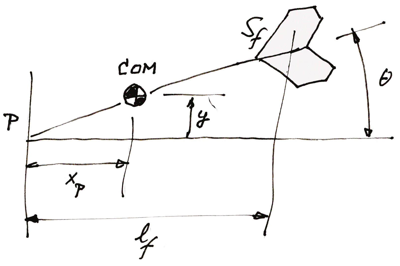
Figure 3 : Dart center of percussion
Let us check a few special cases which seem simple at first, but which turn out to be rather subtle.
First, suppose the dart has only a point mass at the COM, and a zero weight stem and fin. In this case the moment of inertia Ixx of the dart about its COM is zero. This makes the xP of (7) equal to zero. That makes intuitive sense : by inspection, the dart will oscillate about its COM. But the frequency of oscillation is a bit troubling : according to (5) it is infinitely high.
The reason why is not trivial. From the free body diagram, any force on the fin will cause the COM to move sideways too. But even the tiniest of forces at the fin will cause an infinite angular acceleration, so the fin will eliminate any lift force by "evading" it. We might say that the fin presents an effective mass of zero to the lift force. The tail feathers will simply turn out of the wind instantly.
Another "idealized" case is that the dart has a weight distribution with two point masses of ½ m each, one aft at the fin and one an equal distance +lf ahead of the COM. This gives Ixx = 2 . ( ½ m lf 2 ), or Ixx = m . l f2 . Substituting this into (7) gives xP = l f
This makes sense too : the front mass is the center of percussion for a force at the rear mass, a.k.a. the fin. With no real mass in between ( the COM is just a mathematical point, but has no mass of its own ), the lift on the fin affects only the rear mass, and leaves the front mass in place. Effectively, the dart will rotate around the front mass, so this is the center of percussion for the fin lift.
Now look at the general case. It is always possible to write Ixx as :
| (8) |
Figure 4 gives the schematic image. The mass m of the dart is modelled as two equal masses, each of ½ m, situated to both sides of the COM. In other words, all mass on average is at a distance r from the COM. The mass could also have beeen divided over a ring of radius r around the COM. According to (7), we have :
| (9) |
This says that r is the geometrical mean between xP and l f.
If l f is larger than r, then xP is smaller than r, and vice versa. For a dart, this generally means that the center of percussion P is only slightly ahead of the COM.

Figure 4 : Dart moment of inertia
Things are very different for an airplane in pitch. There the AC or neutral point is much closer than r to the COM, which means that the percussion point is very far forward, often ahead of the physical nose of the aircraft.
This further discussed in the section on the short period mode.
An interesting side note is that by (5), the oscillation
frequency is proportional to the flight speed.
This means that the wave length of the oscillation
along the flight path is independent of the flying speed.
It is known that darts are tuned to make one full wave
from launch to board, so the oscillation is at zero
when the dart hits the board.
TBW